instruments
>
analog::blocks
analog::blocks specifications
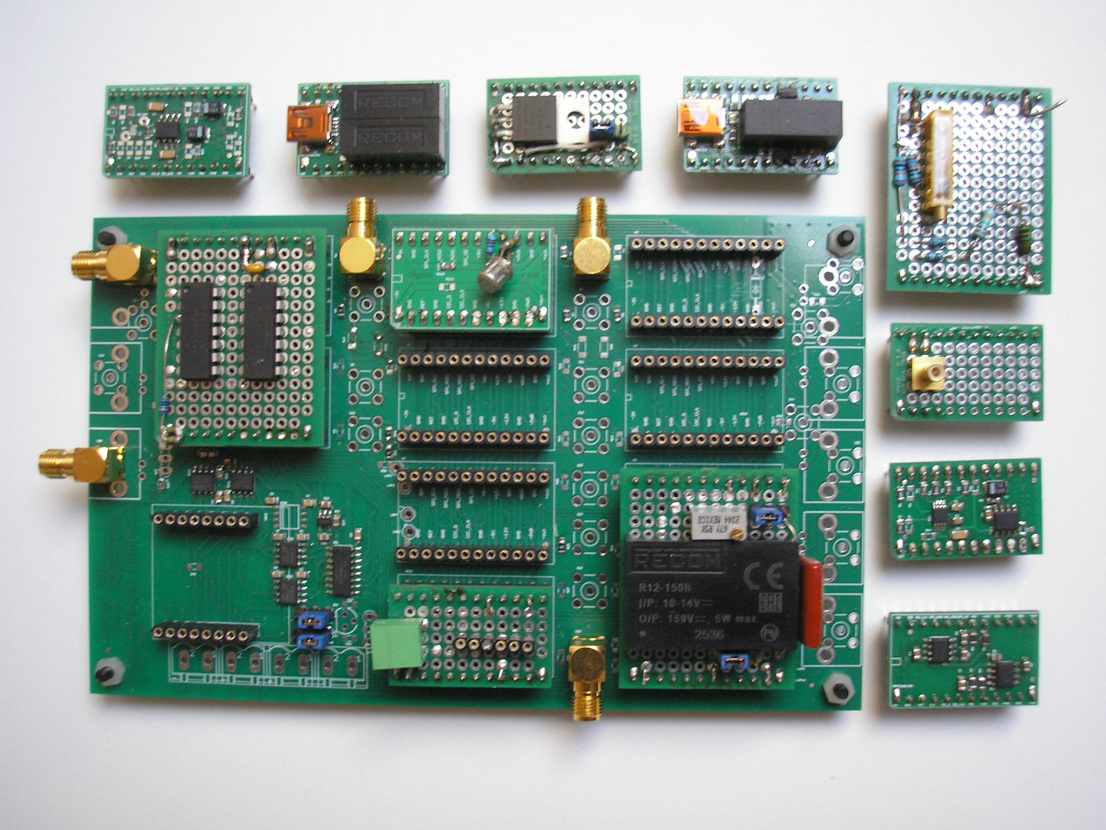
The analog::blocks Baseboard provides power, signal routing and digital interfaces for rapid system development.
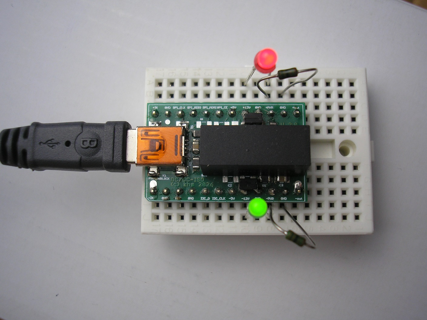
Individual analog::blocks Modules can also be used independently on standard breadboards. The USB DC/DC Module provides ±12 V directly from a USB port.
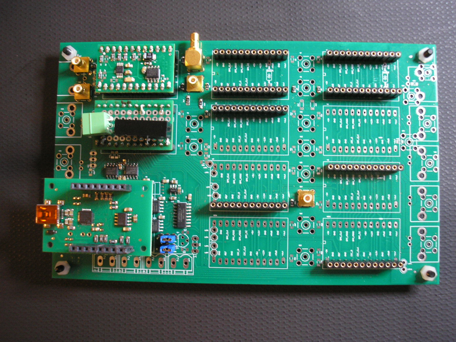
analog::blocks Base Board partial populated
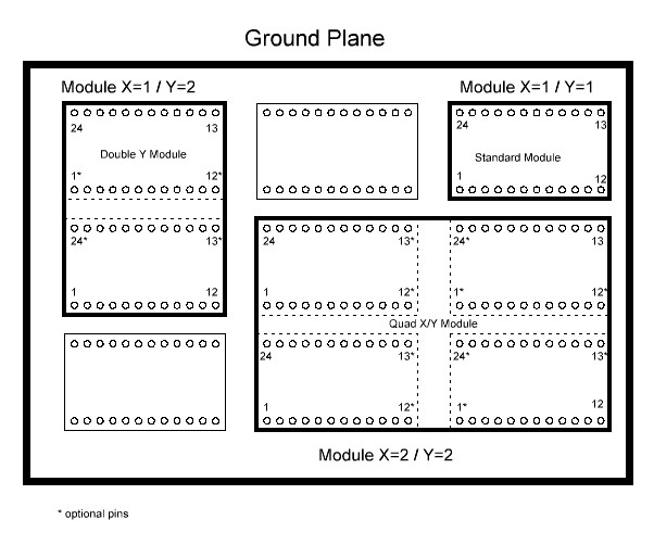
analog::blocks Module Size Flexibility
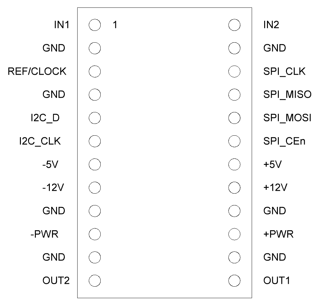
analog::blocks Module Pinout
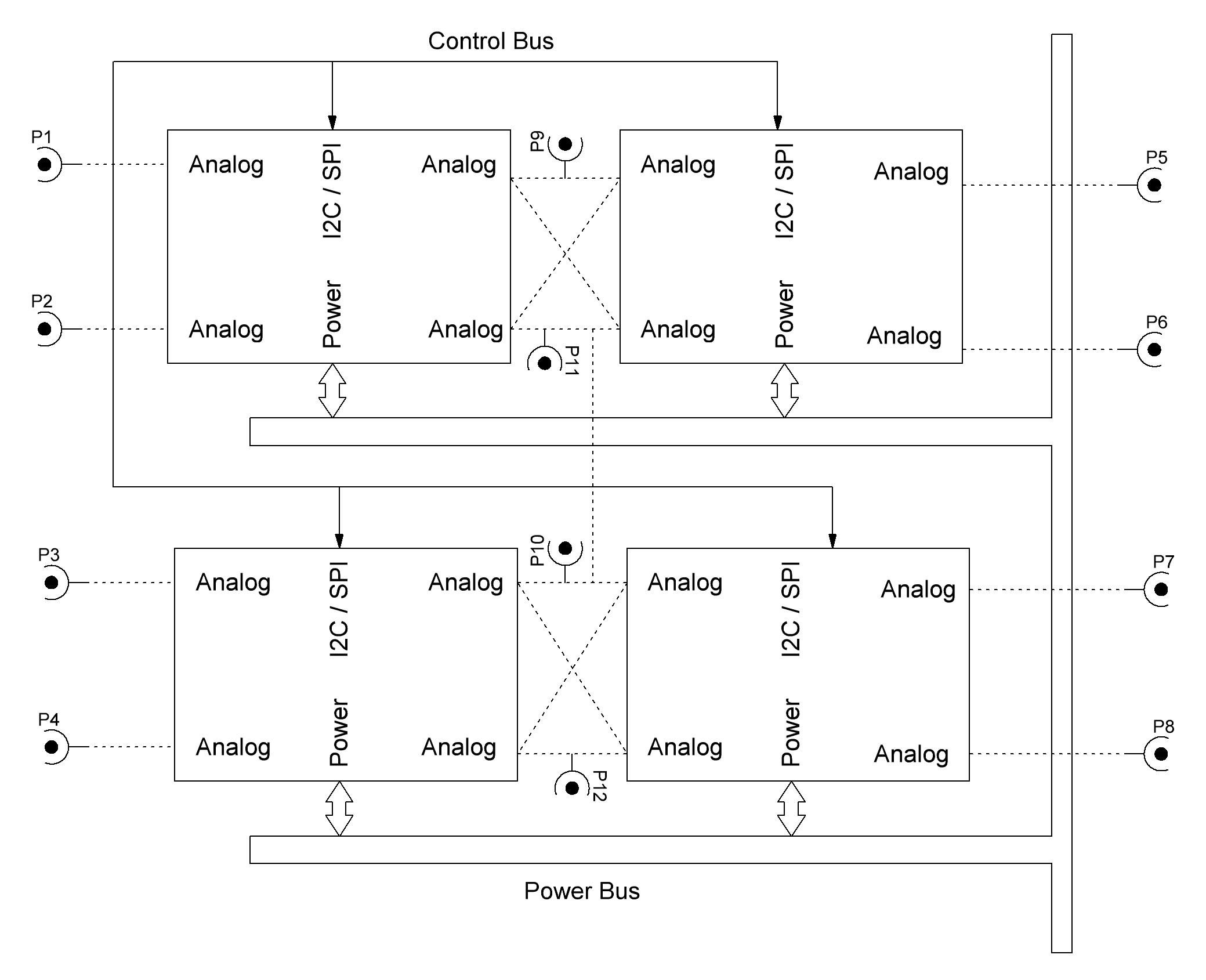
analog::blocks Simplified System Schematic
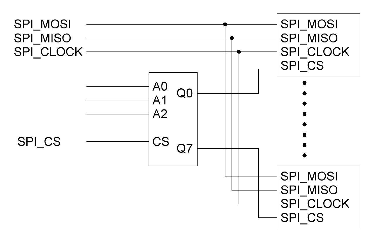
analog::blocks Base Board SPI Chip-Select Multiplexer for up to eight devices
analog::blocks Transmission Line Test Setup
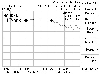
analog::blocks Transmission Line Spectrum
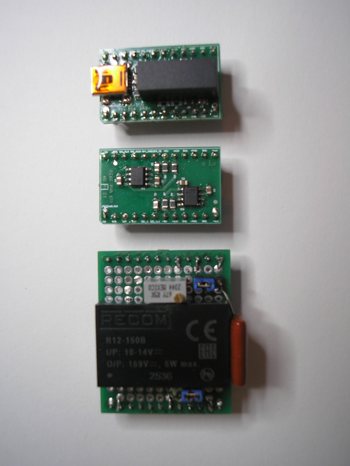
analog::blocks Power Modules
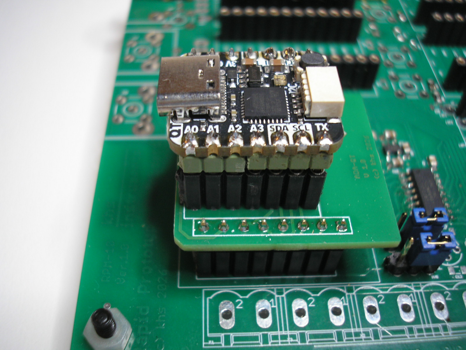
analog::blocks Microcontroller Interface with QT Py Adapter
last update 260720
analog::blocks
Design Philosophy
The objective of analog::blocks is not to replace conventional development boards, but to provide a reusable analog infrastructure that allows engineers to concentrate on circuit design rather than rebuilding the surrounding hardware.
By combining standardized analog interconnections, flexible mechanics, modular power distribution, scalable digital interfaces and rapid measurement access, analog::blocks transforms prototype development into a collection of reusable hardware building blocks.
The Baseboard provides standardized analog interconnections, power distribution and digital interfaces. As a result, Prototype Blocks only need to implement the circuit under evaluation, significantly reducing development effort.
By combining standardized analog interconnections, flexible mechanics, modular power distribution, scalable digital interfaces and rapid measurement access, analog::blocks transforms prototype development into a collection of reusable hardware building blocks.
The Baseboard provides standardized analog interconnections, power distribution and digital interfaces. As a result, Prototype Blocks only need to implement the circuit under evaluation, significantly reducing development effort.
analog::blocks specifications
The analog::blocks Baseboard provides power, signal routing and digital interfaces for rapid system development.
Universal Hardware Platform
The standard DIL interface also allows individual blocks to be used independently on conventional breadboards.
Prototype Boards add compact 100 mil /50 mil prototyping areas to conventional breadboards, allowing circuits that are difficult to build directly on a breadboard.
Prototype Boards add compact 100 mil /50 mil prototyping areas to conventional breadboards, allowing circuits that are difficult to build directly on a breadboard.
Individual analog::blocks Modules can also be used independently on standard breadboards. The USB DC/DC Module provides ±12 V directly from a USB port.
Project-Oriented Development
The Baseboard is intended to be configured for each individual project.
Only the connectors and jumper links required by the application need to be populated, reducing assembly effort and cost. Low-cost unpopulated Baseboards make it practical to dedicate a Baseboard to each project while preserving previous hardware configurations.
Only the connectors and jumper links required by the application need to be populated, reducing assembly effort and cost. Low-cost unpopulated Baseboards make it practical to dedicate a Baseboard to each project while preserving previous hardware configurations.
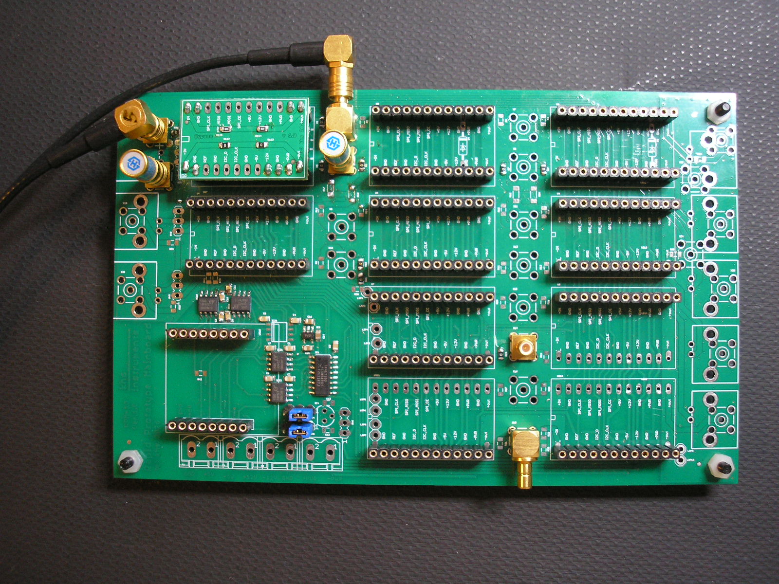
analog::blocks Base Board partial populated
Flexible Module Dimensions
Unlike conventional modular systems, analog::blocks does not restrict module size. Each Function Block can use the board area required by its circuitry, from small analog interfaces to large power amplifier modules.
The flexible mechanical concept also simplifies adapter boards for existing module standards such as mikroBUS™ Click Boards while maintaining compatibility with the analog::blocks architecture.
The flexible mechanical concept also simplifies adapter boards for existing module standards such as mikroBUS™ Click Boards while maintaining compatibility with the analog::blocks architecture.
analog::blocks Module Size Flexibility
Optimized Connector Layout
The connector layout is designed as a compromise between analog performance, flexibility and connector density.
Critical analog signals are located at the edges of the module interface with adjacent ground connections providing controlled return paths and improved shielding. Ground pins are also placed next to the power rails to reduce the risk of accidental cross-connections between different supply voltages.
Digital interfaces and standard power rails share connector resources where appropriate, allowing up to ten standard modules plus an isolated digital interface on a Eurocard-sized Baseboard.
Dedicated pins for the ±5 V and ±12 V supply rails allow modules to use the required voltage without manual supply selection, reducing the risk of accidental overvoltage.
Critical analog signals are located at the edges of the module interface with adjacent ground connections providing controlled return paths and improved shielding. Ground pins are also placed next to the power rails to reduce the risk of accidental cross-connections between different supply voltages.
Digital interfaces and standard power rails share connector resources where appropriate, allowing up to ten standard modules plus an isolated digital interface on a Eurocard-sized Baseboard.
Dedicated pins for the ±5 V and ±12 V supply rails allow modules to use the required voltage without manual supply selection, reducing the risk of accidental overvoltage.
analog::blocks Module Pinout
Two-Dimensional System Architecture
Rather than using a fixed linear backplane, analog::blocks distributes modules across a two-dimensional Baseboard. This allows efficient use of PCB area while supporting modules of different sizes and functions.
The architecture is independent of Baseboard size. Compact Baseboards for rapid experiments and larger Eurocard-sized systems use the same module interface and remain fully compatible.
The architecture is independent of Baseboard size. Compact Baseboards for rapid experiments and larger Eurocard-sized systems use the same module interface and remain fully compatible.
analog::blocks Simplified System Schematic
Scalable and Galvanically Isolated Digital Interfaces
Common digital buses such as SPI and I²C are shared across multiple modules and electrically isolated from the analog system.
Galvanic isolation minimizes ground loops and interference caused by ground potential differences, while allowing the analog reference potential to be defined independently for each application.
An addressable SPI chip-select multiplexer allows up to eight SPI devices to be controlled without requiring individual chip-select lines from the host, enabling complex mixed-signal systems with minimal interface overhead.
Galvanic isolation minimizes ground loops and interference caused by ground potential differences, while allowing the analog reference potential to be defined independently for each application.
An addressable SPI chip-select multiplexer allows up to eight SPI devices to be controlled without requiring individual chip-select lines from the host, enabling complex mixed-signal systems with minimal interface overhead.
analog::blocks Base Board SPI Chip-Select Multiplexer for up to eight devices
High Signal Integrity
The architecture is optimized for low-noise analog design.
Ground connections surround critical analog signal paths, while optional SMA or SMB connectors allow analog signals to be routed outside the system for direct characterization, debugging and measurement.
Prototype Blocks can therefore be assembled within minutes to evaluate bandwidth, crosstalk, noise or other analog parameters without designing dedicated evaluation hardware.
Ground connections surround critical analog signal paths, while optional SMA or SMB connectors allow analog signals to be routed outside the system for direct characterization, debugging and measurement.
Prototype Blocks can therefore be assembled within minutes to evaluate bandwidth, crosstalk, noise or other analog parameters without designing dedicated evaluation hardware.
analog::blocks Transmission Line Test Setup
analog::blocks Transmission Line Spectrum
Modular Power Architecture
Multiple standardized supply rails support both traditional and modern analog circuits.
Standard analog rails include ±12 V and ±5 V, while higher voltages such as ±30 V are provided by dedicated power modules using separate supply paths for high-power applications.
Power can be supplied through dedicated power connectors or generated locally by power modules. For example, a USB-powered DC/DC converter module can inject the required supply rails directly into the Baseboard.
Power modules can also be stacked, allowing functions such as USB power conversion, ±12 V generation and ±5 V regulation to be combined from reusable building blocks.
Standard analog rails include ±12 V and ±5 V, while higher voltages such as ±30 V are provided by dedicated power modules using separate supply paths for high-power applications.
Power can be supplied through dedicated power connectors or generated locally by power modules. For example, a USB-powered DC/DC converter module can inject the required supply rails directly into the Baseboard.
Power modules can also be stacked, allowing functions such as USB power conversion, ±12 V generation and ±5 V regulation to be combined from reusable building blocks.
analog::blocks Power Modules
Open Hardware Ecosystem
Dedicated interface modules enable integration of established hardware ecosystems.
Feather-compatible controller boards provide immediate access to a wide range of processors and communication modules, while adapter boards support mikroBUS™ Click Boards and other standard interfaces.
Standard communication buses allow developers to reuse existing software libraries without locking projects to a specific software framework.
Feather-compatible controller boards provide immediate access to a wide range of processors and communication modules, while adapter boards support mikroBUS™ Click Boards and other standard interfaces.
Standard communication buses allow developers to reuse existing software libraries without locking projects to a specific software framework.
analog::blocks Microcontroller Interface with QT Py Adapter
last update 260720